


SCR
A silicon controlled rectifier or semiconductor-controlled rectifier is a four-layer solidstate current-controlling device. The name "silicon controlled rectifier" is General Electric's trade name for a type of thyristor.
SCRs are mainly used in electronic devices that require control of high voltage and power. This makes them applicable in medium and high AC power operations such as motor control function.
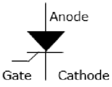
An SCR conducts when a gate pulse is applied to it, just like a diode. It has four layers of semiconductors that form two structures namely; NPNP or PNPN. In addition, it has three junctions labeled as J1, J2 and J3 and three terminals(anode, cathode and a gate). An SCR is diagramatically represented as shown below.
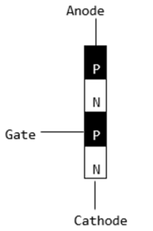
The anode connects to the P-type, cathode to the N-type and the gate to the P-type as shown below.
In an SCR, the intrinsic semiconductor is silicon to which the required dopants are infused. However, doping a PNPN junction is dependent on the SCR application.
Modes of Operation in SCR
OFF state (forward blocking mode) − Here the anode is assigned a positive voltage, the gate is assigned a zero voltage (disconnected) and the cathode is assigned a negative voltage. As a result, Junctions J1 and J3 are in forward bias while J2 is in reverse bias. J2 reaches its breakdown avalanche value and starts to conduct. Below this value, the resistance of J1 is significantly high and is thus said to be in the off state.
ON state (conducting mode) − An SCR is brought to this state either by increasing the potential difference between the anode and cathode above the avalanche voltage or by applying a positive signal at the gate. Immediately the SCR starts to conduct, gate voltage is no longer needed to maintain the ON state and is, therefore, switched off by −
Decreasing the current flow through it to the lowest value called holding current
Using a transistor placed across the junction.
Reverse blocking − This compensates the drop in forward voltage. This is due to the fact that a low doped region in P1 is needed. It is important to note that the voltage ratings of forward and reverse blocking are equal.


0 comments:
Post a Comment