This is default featured slide 1 title

Go to Blogger edit html and find these sentences.Now replace these sentences with your own descriptions.

This is default featured slide 2 title

Go to Blogger edit html and find these sentences.Now replace these sentences with your own descriptions.

This is default featured slide 3 title

Go to Blogger edit html and find these sentences.Now replace these sentences with your own descriptions.

This is default featured slide 4 title

Go to Blogger edit html and find these sentences.Now replace these sentences with your own descriptions.

This is default featured slide 5 title

Go to Blogger edit html and find these sentences.Now replace these sentences with your own descriptions.

Showing posts with label CIRCUIT THEORY. Show all posts

Initial value and Final value theorem


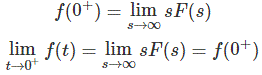
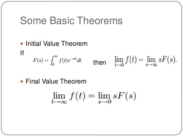
Initial value theorem:


If f(t) and F(s) is Laplace transform pairs. i.e


then Initial value theorem is given by


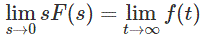
Final value theorem:


If f(t) and f'(t) both are Laplace Transformable and sF(s) has no pole in jw axis

and in the R.H.P. i.e Right half Plane then,


                                                           = f(infinite)


ACTIVE,REACTIVE,APPARENT AND COMPLEX POWER


REAL POWER: 
Real Power is the actual power which is really transferred to the load such as motors,transformers etc.,
Alternative words used for Real Power (Actual Power, True Power, Watt-full Power, Useful Power, Real Power, and Active Power) and denoted by (P) and measured in units of Watts (W) i.e. The unit of Active or Real power is Watt where 1W = 1V x 1 A.

Real Power in DC Circuits:
In DC Circuits, power supply to the DC load is simply the product of Voltage across the load and Current flowing through it i.e., P = V I because in DC Circuits, there is no concept of phase angle between current and voltage. In other words, there is no frequency (f) or powe factor in DC Circuits.
Real Power in AC Circuits:

But the situation in Sinusoidal or AC Circuits is more complex because of phase difference (θ) between Current and Voltage. Therefore average value of power (Real Power) is P = VI Cosθ is in fact supplied to the load.

Real Power formulas:
P = V I (In DC circuits)
P = VI Cosθ (in Single phase AC Circuits)
P = √3 VL IL Cosθ or (in Three Phase AC Circuits)
P = 3 VPh IPh Cosθ

Reactive Power: (Q) 

It is also  known as (Use-less Power, Watt less Power)

Power merely absorbed and returned in load due to its reactive properties is referred to as reactive power. denoted by Q

Reactive power represent that the energy is first stored and then released in the form of magnetic field or electrostatic field in case of inductor and capacitor respectively.

Reactive power is given by Q = V I Sinθ which can be positive (+ve) for inductive loads and negative (-Ve) for capacitive load.

The unit of reactive power is Volt-Ampere reactive i.e. VAR where 1 VAR = 1V x 1A.
In Inductor or Capacitor, how much magnetic or electric field made by 1A x 1V is called the unit of reactive power.


Apparent Power: (S)

The combination of reactive power and true power is called apparent power

In an AC circuit, the product of the r.m.s voltage and the r.m.s current is called apparent power which is denoted by (S) and measured in units of Volt-amp (VA).
S=V*I

It is the product of Voltage and Current without phase angle.

The unit of Apparent power (S) VA i.e. 1VA = 1V x 1A.

When the circuit is pure resistive, then apparent power is equal to real or true power, but in inductive or capacitive circuit, (when Reactances exist) then apparent power is greater than real or true power.


Complex Power: (S )

The Complex sum of Real Power (P) and Reactive Power (Q) is known as Complex Power which can be expressed like S = P+jQ and measured in terms of Volt Amps Reactive (generally in kVAR).

It may also be expressed as S=VI* where I* is the conjugate of the complex current I. This current “I” flows through a reactive load Z caused by the Voltage.


flemings left hand rule


for motor


gate eee

gate eee basics


flemming right hand rule for generator


gate eee

difference between lumped and distributed elements?


lumped circuit is a circuit of visible & physical present elements like R L & C 

whereas ..

distributed parameters also like R L & C are invisible & physical not present but they are effectively distributed throughout the transmission line & useful for calculation.and also an element of R,L,C of a circut can be seperated then these elements are said to be lumped elements otherwise these are said to be distributed elements.


Main Difference between contactor and Starter

The magnetic starter is very similar to the magnetic contactor in design and operation. Both have the feature of operating contacts when the coil is energized. The important difference between contactorsand starters is the use of overload heater element in the starter.


Difference between Active and Passive elements


Difference between Active and Passive Components

Active Components:Those devices or components which required external source to their operation is called Active Components. Example :Diode, Transistors etc..Passive Components:Those devices or components which do not required external source to their operation is called Passive Components. 


Example: Resistor, Capacitor, Inductor etc…


Difference between Unilateral and Bi-Lateral Circuits & Elements


Difference between Unilateral and Bi-Lateral Circuits & Elements:

Unilateral circuits:


diode


The property of circuit changes with the change of direction of the supply voltage or current. In other words, the unilateral circuit allows the current to flow only in one direction. Diode rectifier is the best example of the unilateral circuit because it does not perform the rectification in both directions of supply.Bi-lateral circuits The property of circuit does not change with the change of direction of the supply voltage or current. In other words, the bilateral circuit allows the current to flow in both directions. Transmission line is the best example of bilateral circuit because, if you give supply from any direction, te circuit properties remain constant

Difference between Linear and Nonlinear Circuit


The Main Difference between Linear and Nonlinear Circuit


1.Linear Circuit:

In simple words, a linear circuit is an electric circuit in which circuit parameters (Resistance, inductance, capacitance, waveform, frequency etc) are constant. In other words, a circuit whose parameters are not changed with respect to Current and Voltage is called Linear Circuit.

2.Non-Linear Circuit 

A nonlinear circuit is an electric circuit whose parameters are varied with respect to Current and Voltage. In other words, an electric circuit in which circuit parameters (Resistance, inductance, capacitance, waveform, frequency etc) is not constant, is called Non-Linear Circuit.
3.Examples of Non-Liner Circuits and Non-Linear Elements
Diode
Transistor
Transformer
Iron Core

transistor Examples of Liner Circuits and Linear Elements
Resistance and Resistive Circuit
Inductor and Inductive Circuits
Capacitor and Capacitive Circuits