This is default featured slide 1 title

Go to Blogger edit html and find these sentences.Now replace these sentences with your own descriptions.

This is default featured slide 2 title

Go to Blogger edit html and find these sentences.Now replace these sentences with your own descriptions.

This is default featured slide 3 title

Go to Blogger edit html and find these sentences.Now replace these sentences with your own descriptions.

This is default featured slide 4 title

Go to Blogger edit html and find these sentences.Now replace these sentences with your own descriptions.

This is default featured slide 5 title

Go to Blogger edit html and find these sentences.Now replace these sentences with your own descriptions.

Showing posts with label POWER ELECTRONICS. Show all posts

DAMPING TYPES


Damping:
It decreases the amplitude of an electrical or mechanical wave. This decrease is due to an energy absorbing mechanism or resistance circuit . A reduction in the amplitude of an oscillation or vibration as a result of energy being dissipated as heat.
The damping of the RLC circuit affects the way the voltage response reaches its final (or steady state) value.
1.when  R^2 > (4L/C) which means there are two real roots and relates to the case when the circuit is said to be over damped
2.when  R^2 <(4L/C) which means there are two complex roots (as root( -1) is imaginary) and relates to the case when the circuit is said to be under damped
3.when  R^2 = (4L/C) which means that the two roots of the equation are equal (i.e. there is only one root) and relates to the case when the circuit is said to be critical damped.
4.when  R=0  ,the circuit is said to be Un damped

RLC CIRCUIT


electrical drive-1

 Electrical Drive:
Whenever the term electric motor or electrical generator is used, we tend to think that the speed of rotation of these machines is totally controlled only by the applied voltage  and frequency of the source current. But the speed of rotation of an electrical machine can be controlled precisely also by implementing the concept of drive. The main advantage of this concept is, the motion control is easily optimized with the help of drive. In very simple words, the systems which control the motion of the electrical machines, are known as electrical drives.
 A typical drive system is assembled with a electric motor (may be several) and a sophisticated control system that controls the rotation of the motor shaft. Now days, this control can be done easily with the help of software. So, the controlling becomes more and more accurate and this concept of drive also provides the ease of use.This drive system is widely used in large number of industrial and domestic applications like factories, transportation systems, textile mills, fans, pumps, motors, robots etc.


Phase Controlled Converter


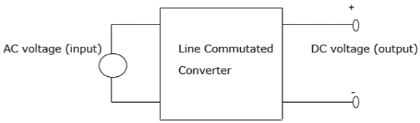
A phase controlled converter converts AC to DC energy (line commutated). In other words, it is used in the conversion of fixed-frequency and fixed-voltage AC power into variable DC voltage output. It is expressed as 


Fixed Input − Voltage, frequency and AC power 


Variable output − DC voltage output 


The AC input voltage that goes into a converter is normally at fixed RMS (root mean square) and fixed frequency. The inclusion of phase-controlled thyristors in the converter ensures that a variable DC output voltage is obtained. This is made possible by altering the phase angle at which the thyristors are triggered. As a result, a pulsating waveform of the load current is obtained.


During the input supply half cycle, the thyristor is in forward bias and is switched ON via the application of sufficient gate pulse (trigger). Current starts to flow once the thyristor has been switched ON, that is, at a point ωt=α to point ωt=β. The moment the load current drops to zero, the thyristor switches OFF as a result of line (natural) commutation.


There are a number of power converters that utilize natural commutation. These include − 
AC to DC converters 
AC to AC converters 
AC voltage controllers 
Cycloconverters

SILICON CONTROLLED RECTIFIER(SCR)


SCR

A silicon controlled rectifier or semiconductor-controlled rectifier is a four-layer solidstate current-controlling device. The name "silicon controlled rectifier" is General Electric's trade name for a type of thyristor.

SCRs are mainly used in electronic devices that require control of high voltage and power. This makes them applicable in medium and high AC power operations such as motor control function.


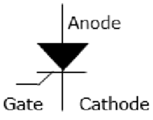
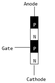
An SCR conducts when a gate pulse is applied to it, just like a diode. It has four layers of semiconductors that form two structures namely; NPNP or PNPN. In addition, it has three junctions labeled as J1, J2 and J3 and three terminals(anode, cathode and a gate). An SCR is diagramatically represented as shown below.


The anode connects to the P-type, cathode to the N-type and the gate to the P-type as shown below.


In an SCR, the intrinsic semiconductor is silicon to which the required dopants are infused. However, doping a PNPN junction is dependent on the SCR application.


Modes of Operation in SCR 


OFF state (forward blocking mode) − Here the anode is assigned a positive voltage, the gate is assigned a zero voltage (disconnected) and the cathode is assigned a negative voltage. As a result, Junctions J1 and J3 are in forward bias while J2 is in reverse bias. J2 reaches its breakdown avalanche value and starts to conduct. Below this value, the resistance of J1 is significantly high and is thus said to be in the off state. 


ON state (conducting mode)An SCR is brought to this state either by increasing the potential difference between the anode and cathode above the avalanche voltage or by applying a positive signal at the gate. Immediately the SCR starts to conduct, gate voltage is no longer needed to maintain the ON state and is, therefore, switched off by − 

Decreasing the current flow through it to the lowest value called holding current 

Using a transistor placed across the junction. 

Reverse blocking This compensates the drop in forward voltage. This is due to the fact that a low doped region in P1 is needed. It is important to note that the voltage ratings of forward and reverse blocking are equal.

triac


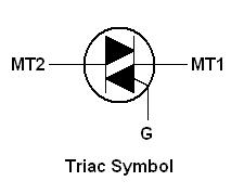
TRIAC is equivalent to two SCRs connected in inverse parallel with the gates connected together. As a result, the TRIAC functions as a Bidirectional switch to pass the current in both directions once the gate is triggered. TRIAC is a three terminal device with a Main terminal1 ( MT1), Main terminal 2( MT2) and a Gate. The MT1 and MT2 terminals are used to connect the Phase and Neutral lines while the Gate is used to feed the triggering pulse. The Gate can be triggered either by a positive voltage or negative voltage. When the MT2 terminal gets a positive voltage with respect to the MT1 terminal and the Gate gets a positive trigger, then the left SCR of the TRIAC triggers and circuit completes. But if the polarity of the voltage at the MT2 and MT1 terminals is reversed and a negative pulse is applied to the Gate, then the right SCR of Triac conducts. When the Gate current is removed, the TRIAC switches off. So a minimum holding current Ih must be maintained at the gate to keep the TRIAC conducting.

Triggering a TRIAC


Usually 4 modes of triggering is possible in TRIAC:
A positive voltage at MT2 and a positive pulse at the gate
A positive voltage at MT2 and a negative pulse at the gate
A negative voltage at MT2 and positive pulse at the gate
A negative voltage at MT2 and a negative pulse at the gate

basics of power electronics


Electricity:

Electricity is a very convenient form of energy. It is relatively easy to produce in bulk in power stations whether they be coal-fired, oil-fired or nuclear (using steam turbines to drive the generators) or hydro (using water turbines to drive the generators).


Energy sources:

There are two basic variables in electric circuits, namely electric current and electric potential difference (which we will often call voltage for short). A source of energy is required to cause a current to flow and thereby to produce electric voltages in various parts of the circuit.


Voltage source:

An ideal voltage source is independent of the current through it. Its electromotive force (emf) or voltage is a function of time only. If a thick copper wire were connected across its ends the current through it would be infinite. The symbol for an ideal voltage source is shown


Current source:
An ideal current source is independent of the voltage across it and if its two ends are not connected to an external circuit the potential difference across it would be infinite.


Resistivity:

The resistance of a conductor is directly proportional to its length (l) and inversely proportional to its cross-sectional area (A).
Mathematically then


R ≈ l/A.
This may also be written as


R = ρl/A


where ρ is the constant of proportionality and is called the resistivity of the material of the conductor.
The unit of ρ is therefore the ohm-metre.
Sometimes it is convenient to use the reciprocal of resistance which is called conductance (G) for which the unit is the siemens (S).


Conductance (G):
It is measure of material's ability to allow the flow of charge.


Alternating Current:
It is the current in which the magnitude and direction vary periodically.


Cycle:
One complete set of change in value and direction of alternating quantities is called as cycle


Period:
It is the time taken to complete one cycle.
The symbol is T


Frequency:
The number of cycles completed per second is known as frequency of the alternating current.
The unit is Hertz (Hz). f=1/T


Instantaneous value:
The value of an alternating quantity at a particular instant in a cycle is called instantaneous value.


Peak value:
The maximum value of an alternating quantity during a cycle is called its peak value.


Phase:
The development of an ac quantity through different stages as known as phase.


In-phase:
When two alternating quantities reach their maximum and minimum value simultaneously, then these quantities are said to be in-phase.


Out-of-Phase:
When two alternating quantities do not attain their maximum and minimum values simultaneously then they are at out of phase.
It is also known as phase difference.


Phase angle:
It is an angular displacement between two alternating quantities.


Average Value:
The arithmetical average of all the values of an alternating quantity over one cycle is called average value.


Average Value = Area under the curve/ Base (period)


Root Mean Square Value (RMS Value)


The rms value of an alternating current is defined as that steady current which when flowing through a given resistance for a given time produces the same amount of heat as produced by the alternating current when flowing through the same resistance for the same time.
It is also known as effective value of an alternating current.


IRMS = √[Area under the squared wave/ Period]


Form Factor:


The ratio of RMS value to average value of an alternating quantity is called form factor.

Form factor = RMS value/ Average value


Peak Factor:

The ratio of maximum value to the RMS value of an alternating quantity is called as peak factor.

Peak factor = Maximum value/ RMS value

damping


Damping

In practice, the amplitude of vibrations becomes progressively smaller as energy is lost due to friction between the oscillating body and the particles in the air.


If energy is being removed from the system, the amplitude of the oscillations must become smaller and smaller, we say that the oscillations are being damped.
The amplitude of oscillations decrease with time.
The higher the damping, the faster the oscillations will reduce in size.


Critical damping is the damping required to make the oscillations stop in the quickest possible time without going past the equilibrium position.


Hit anything and it will vibrate. The amazing thing is that every time you hit it, it will vibrate with exactly the same frequency, no matter how hard you hit it.


The frequency of un-damped oscillations in a system, which has been allowed to oscillate on its own, is called the natural frequency, f0.


In order to keep it vibrating after you've hit it, you need to keep re-hitting it periodically to make up for the energy being lost. We say that you need to apply a periodic force to it. (Although some people would just say that you are being unnecessarily violent.)


The frequency with which the periodic force is applied is called the forced frequency. If the forced frequency equals the natural frequency of a system (or a whole number multiple of it) then the amplitude of the oscillations will grow and grow. This effect is known as resonance.


basics2


KIRCHOFF’S VOLTAGE LAW: KVL is based on the law of the law of conservation of the energy, states that the algebraic sum of voltage drops in a closed loop is zero.{Flow of currents in loop is assumed +ve from higher potential to lower potential in elements and +ve from lower to higher potential in Sources}.
NODES, BRANCHES AND LOOPS:
Network is an interconnection of elements or devices, circuit is a network providing one or more closed paths
A BRANCH represents a single element such as voltage source or a resistor.
A NODE is the point of connection of two or more branches.
A LOOP is any closed path in a circuit. A network with ‘b’ branches, ‘l’ loops and ‘n’ nodes should satisfy the theorem of n/w topology.(b =l +n – 1).
SERIES ELEMENTS AND VOLTAGE DIVISION Two or more elements are in series if they are cascaded or connected sequentially and consequently carry the same current. The equivalent resistances of any number of resistors connected in series is the sum of the individual resistances.
DEPENDENT OR CONTROLLED SOURCES: In some network, in which some of the voltage sources or current sources are controlled by changing of current or voltage elsewhere in the circuit. Such sources are termed as “Dependent or Controlled sources”. There are four types of dependent sources.i.CDVS( Current DVS), ii.CDCS(Current DCS) ,iii.VDVS(Voltage DVS) iv.VDCS(Voltage DCS).
SOURCE TRANSFORMATION: A practical voltage source can be replaced by a current source and vice versa. This can be established if an equivalence between a voltage source and a current source.

basics1


To do anything we need basics.so first we will go with basics

Basic Laws: Ohm’s law, Kirchhoff’s voltage and current laws, Nodes-Branches and loops, Series elements and Voltage Division, Parallel elements and Current Division, Star-Delta transformation, Independent sources and Dependent sources, source transformation. 


OHM’S LAW : At constant temperature, the current flowing through a conductor is directly proportional to the potential difference(p.d) in volts across the two ends of the given conductor and inversely proportional to the resistance (R) in ohms (Ω) between the ends of the same conductor. 


In all practical problems of electrical calculations, it is assumed that the temperature rise is within limits, so that electrical properties such as insulation and conduction properties of the given materials are not destroyed.

hence ohms law mathematically stated as I=V/R or V=IR.


KIRCHOFF’S CURRENT LAW : KCL states that the total current entering a junction is equal to the total current leaving the junction. 


(or)

The algebraic sum of the currents at the junction (node) will be zero.